Page 164 - TBIS_15194-2019_(EN)_3nd
P. 164
TBIS 15194:2019
Here, P2: driving output of the bicycle after correction (W)
P2': Driving output of the bicycle before correction (W)
Pcl: power loss of test machine (W)
And, the unit is expressed by Watt (W), which is set as an integral (please
st
round off to the 1 decimal place).
d) Assistant force ratio: α
α= (P2-P1) / P1
P1: revolution input of crank (W)
P2: driving output of the bicycle after correction (W)
nd
rd
And, the expressed place is the 2 place (please round off to the 3 decimal
place).
6. Test device
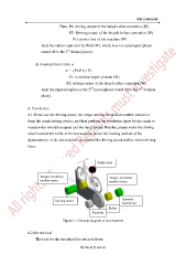
6.1 Please use the driving motor, the torque and the revolution number sensors to
form the crank driving device, and then perform the revolution input for the crank to
measure the revolution speed and the input torque. Besides, please make the driving
wheel contact the roller of the test machine to use the loading method of the
dynamometer of the test machine to measure the driving speed and the wheel driving
force.
Saddle load
Torque, revolution Torque, revolution
number sensor number sensor
Dynamic
Driving motor
load device
Roller
Flywheel
Figure L1 Concept diagram of test machine
6.2 Set test load
The load for the test should be set as follows:
第 156 頁共 162 頁