Page 161 - TBIS_15194-2019_(EN)_3nd
P. 161
TBIS 15194:2019
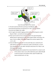
Saddle load
Torque, revolution Torque, revolution
number sensor number sensor
Dynamic
Driving motor
load device
Roller
Flywheel
Figure K1 Concept diagram of test machine
8. The test should be performed according to the following order:
a) Put the electrically power assisted bicycle for test on the test machine.
b) Put the load of 60kg on the saddle.
c) Set the speed, the speed-changing position of the electrically power assisted
bicycle in Table 1, and set the driving impedance.
d) Please use the external motor to drive the crank of the electrically power
assisted bicycle to generate the roller surface speed in Table 1 according to the
type of the test method. The variation range of the revolution speed of the
crank is ±2%.
e) Please test the driving distance from the electrically power assisted bicycle’s
crank starting to revolve to the electrically power assisted bicycle’s assistant
force stopping (Note 2); the unit for resting the endurance is km. Please round
off to the 2 nd decimal place.
Note (2): the stopping of the assistant force means that the force output current
of the assistant motor is cut and the electrically power assisted bicycle
cannot be assisted by the assistant motor even if the electrically
power assisted bicycle is driving.
第 153 頁共 162 頁