Page 20 - 20190101 part 6 (EN)
P. 20
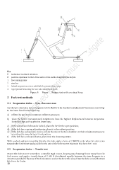
Key
E horizontal, rearward extension
H position equivalent to that of the centre of the saddle clamp with the bicycle
1 free-running roller
2 steel bar
3 locked suspension unit or solid link for pivoted chain stays
4 rigid, pivoted mounting for rear axle attachment point
Figure 5 — Frame — Fatigue test with a vertical force
5 Fork test methods
5.1 Suspension forks — Tyre-clearance test
For the tyre-clearance test, a suspension fork shall first be checked and adjusted if necessary according
to the items listed in the following:
a) inflate the tyre to the maximum inflation pressure;
b) place the fork in uncompressed condition to have the highest displacement between suspension
stanchion legs and suspension lower legs;
c) if the suspension fork can be locked, place the fork in the open position;
d) if the fork has a spring adjust device, place it in the softest position;
e) if the fork has a pneumatic device, inflate the one or the two chambers at their minimum pressures
according the manufacturer’s instruction;
f) if the fork has a rebound device, place it on the slowest position.
With a wheel and tyre assembly fitted to the fork, apply a force of 2 800 N to the wheel in a direction
towards the fork-crown and parallel to the axis of the fork steerer. Maintain this force for 1 min.
5.2 Suspension forks — Tensile test
Mount the fork steerer securely in a suitable rigid mount, keeping any clamping forces away from the
fork-crown, and apply a tensile force of 2 300 N distributed equally between the two dropouts in a
direction parallel to the axis of the fork steerer and in the direction away from the fork crown. Maintain
this force for 1 min.
12