Page 17 - 20190101 part 6 (EN)
P. 17
In tests on suspension frames with pivoted joints, lock the moving part of the frame into a position as
would occur with an 80 kg rider seated on the bicycle. This can be achieved by locking the suspension
unit in an appropriate position or, if the type of suspension system does not permit it to be locked, then
the suspension system can be replaced by a solid link of the appropriate compressed size. Ensure that
the axes of the front and rear axles are horizontally in line, as shown in Figure 4. For suspension frames
in which the chain stays do not have pivots but rely on flexing, ensure that any dampers are set to
provide the minimum resistance in order to ensure adequate testing of the frame.
Where a suspension frame has adjustable brackets or linkages to vary the resistance of the bicycle
against the ground-contact forces or to vary the attitude of the bicycle, arrange the positions of these
adjustable components to ensure maximum forces in the frame.
4.4.2 Test method
4.4.2.1 Stage 1
Mount the frame in its normal attitude and secured at the rear dropouts so that it is not restrained in a
rotary sense (i.e. preferably by the rear axle) as shown in Figure 4. Ensure that the axis of the front and
rear axles are horizontally in line.
Apply cycles of dynamic, horizontal forces of Stage 1 F 2 in a forward direction and Stage 1 F 3 in a
rearward direction to the front fork dropouts for Stage 1 C 1 cycles as shown in Ta ble 4 and Figure 4,
with the front fork constrained in vertical direction but free to move in a fore/aft direction under the
applied forces. The maximum test frequency shall be maintained as specified in TBIS 4210-3:2016, 4.5.
If the frame meets the requirement as specified in TBIS 4210-2:2017, 4.8.5, and conduct stage 2 of the
test with the assembly in the same mountings.
4.4.2.2 Stage 2
With the frame and front fork assembly mounted as in 4.4.2.1, Apply cycles of dynamic, horizontal
forces of Stage 2 F2 in a forward direction and Stage 2 F3 in a rearward direction to the front fork
dropouts for Stage 2 C1 cycles as shown in Table 4 and Figure 4, with the front fork constrained in
vertical direction but free to move in a fore/aft direction under the applied forces. The maximum test
frequency shall be maintained as specified in TBIS 4210-3:2016, 4.5.
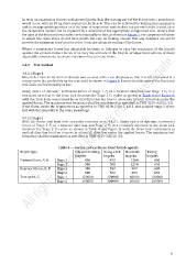
Table 4 — Forces and cycles on front fork dropouts
Bicycle type City and trekking Young adult Mountain Racing
bicycles bicycles bicycles bicycles
Forward force, F2 N Stage 1 450 450 1200 600
Stage 2 500 500 1250 650
Rearward force, F3 N Stage 1 450 450 600 600
Stage 2 500 500 650 650
Test cycles, C1 Stage 1 120000 120000 60000 120000
Stage 2 100000 100000 50000 100000
9