Page 25 - 20190101 part 6 (EN)
P. 25
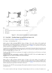
Key
1 front fork
2 fork mounting fixture (fixture representative of the head tube)
3 rigid mount
4 test adaptor
Figure 9 — Fork steerer torsional test (a typical example)
5.5 Front fork — Bending fatigue test and rearward impact test
Mount the fork according to Annex B as shown in Figure 10.
5.5.1 Stage 1- Bending fatigue test
Apply cycles of fully reversed, dynamic forces of Stage 1 F 6 in the plane of the wheel and
perpendicular to the fork steerer tube to a loading attachment and swivel on an axle located in the axle-
slots of the blades for 120 000 test cycles. The forces are given in Table 9. The maximum test frequency
shall be maintained as specified in TBIS 4210-3:2016, 4.5.
Conclude the test if the running displacement (peak-to-peak value) at the point where the test forces are
applied increases by more than 20 % for rigid forks or more than 40 % for suspension forks from the
initial values (see TBIS 4210-3:2016, 4.6).
Stop the test after 120 000 cycles and inspect the sample carefully for fractures. If fractures are found,
conclude the test.
If the fork meets the requirement as specified in TBIS 4210-2:2017, 4.9.6, and conduct stage 2 of
bending fatigue test with the assembly in the same mountings.
5.5.2 Stage 2- Bending fatigue test
Apply cycles of fully reversed, dynamic forces of Stage 2 F 6 in the plane of the wheel and
perpendicular to the fork steerer tube to a loading attachment and swivel on an axle located in the axle-
slots of the blades for 100 000 test cycles. The forces are given in Ta ble 9. The maximum test frequency
shall be maintained as specified in TBIS 4210-3:2016, 4.5
Stop the test after 100 000 cycles and inspect the sample carefully for fractures. If fractures are found,
,conclude the test.
If the sample completes both stage 1 and stage 2 bending fatigue test without exceeding the displacement
17