Page 18 - 20190101 part 6 (EN)
P. 18
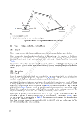
Key
1 free-running guided roller
2 rigid, pivoted mounting for rear-axle attachment point
Figure 4 — Frame — Fatigue test with horizontal forces
4.5 Frame — Fatigue test with a vertical force
4.5.1 General
Where a frame is convertible for male and female riders by the removal of a bar, remove the bar.
Where a suspension frame has adjustable brackets or linkages to vary the resistance of the bicycle
against the ground-contact forces or to vary the attitude of the bicycle, arrange the positions of these
adjustable components to ensure maximum forces in the frame. Secure the rear suspension as described
in 4.3.1.
If a suspension fork is fitted lock it at a length equivalent to that with an 80 kg (in case of young adult
bicycles, apply 40 kg) rider seated on the bicycle either by adjusting the spring/damper or by external
means.
4.5.2 Test method
4.5.2.1 Stage 1
Mount the frame in its normal attitude and secured at the rear dropouts so that is not restrained in a
rotary sense (i.e. preferably by the rear axle) as shown in Figure 5. Fit a suitable roller to the front axle
in order to permit the frame to flex in a fore/aft sense under the test forces.
Insert intended seat post at minimum insertion depth or equivalent to a seat stem to a depth of 75 mm
in the top of the seat tube and secure this to the manufacturer’s instructions by the normal clamp.
Securely attach a horizontal, rearward extension (E in Figure 5) to the top of this bar such that its length
(dimension h 3 in Figure 5) places point H in a position equivalent to that of the centre of the saddle
clamp with the bicycle at its maximum saddle height recommended for the particular frame, or, if the
maximum saddle height information is not available, dimension h 3 shall be 250 mm.
Apply cycles of dynamic, vertically-downward forces of stage 1 F 4 at a point 70 mm behind the
intersection of the axes of the solid steel bar and the extension piece, E, as shown in Figure 5 for 60
000 test cycles. The forces are given in Table 5. The maximum test frequency shall be maintained
as specified in TBIS 4210-3:2016, 4.5.
If the frame meets the requirement as specified in TBIS 4210-2:2017, 4.8.6, and conduct stage 2 of the
test with the assembly in the same mountings.
10