Page 14 - 20190101 part 6 (EN)
P. 14
TBIS 4210-6:2019
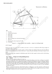
Dimensions in millimetres
Key
1 wheelbase
2 permanent deformation
3 mass 1 (M 1 )
4 mass 2 (M 2 )
5 mass 3 (M 3 )
6 rigid mounting for rear-axle attachment point
7 steel anvil
D distance to the centre of gravity (75 mm)
h 2 drop height
Figure 2 — Frame and front fork assembly — Impact test (falling frame)
4.2.2.2 Stage 2
With the frame and front fork assembly mounted as in 4.2.2.1, increase the 20% of total weight for
each kind of bike at mass 3.
Measure the wheelbase with the three masses in place. Rotate the assembly about the rear axle until the
distance between the low-mass roller and the anvil is h2, then allow the assembly to fall freely to impact on the
anvil.
Repeat the test and then measure the wheelbase again with the three masses in place and the roller resting
on the anvil.
4.3 Frame — Fatigue test with pedalling forces
4.3.1 General
All types of frame shall be subjected to this test.
In tests on suspension frames with pivoted joints, adjust the spring, air pressure, or damper to provide
maximum resistance, or, for a pneumatic damper in which the air pressure cannot be adjusted, replace
the suspension unit with a rigid link, ensuring that its end fixings and lateral rigidity accurately simulate
those of the original unit. For suspension frames in which the chain stays do not have pivots but rely on
flexing, ensure that any dampers are set to provide the minimum resistance in order to ensure adequate
testing of the frame.
Where a suspension frame has adjustable brackets or linkages to vary the resistance of the bicycle
against the ground-contact forces or to vary the attitude of the bicycle, arrange the positions of these
adjustable components to ensure maximum forces in the frame.
6