Page 33 - TBIS_79010-2019_(EN)_1nd
P. 33
TBIS 79010:2019
A
A-A
B-B
F 7.5°
75 F F
45
L
150 150
A
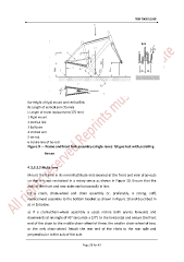
Rw Height of rigid mount and vertical link
Rc Length of vertical arm (75 mm)
L Length of crank replacement (175 mm)
1 Rigid mount
2 Vertical link
3 Ball-joint
4 Vertical arm
5 tie-rod
6 Centre-line of tie-rod
Figure 9 — Frame and front fork assembly (single-lane): fatigue test with pedalling
forces
4.3.3.3.2 Multi-lane
Mount the frame in its normal attitude and secured at the front and rear drop-outs
so that it is not restrained in a rotary sense as shown in Figure 10. Ensure that the
axes of the front and rear axles are horizontally in line.
Fit a crank, chain-wheel and chain assembly or, preferably, a strong, stiff,
replacement assembly to the bottom bracket as shown in Figure 10 and described in
a) or b) below.
a) If a crank/chain-wheel assembly is used, incline both cranks forwards and
downwards at an angle of 45° (accurate ± 2,0°) to the horizontal and secure the front
end of the chain to the middle chain-wheel of three, the smaller chain-wheel of two,
or the only chain-wheel. Attach the rear end of the chain to the rear axle and
perpendicular to the axis of the axle.
Page 29 for 43