Page 36 - TBIS_79010-2019_(EN)_1nd
P. 36
TBIS 79010:2019
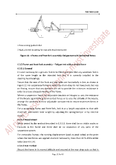
1 Free-running guided roller
2 Rigid, pivoted mounting for rear axle attachment point
Figure 11 —Frame and front fork assembly: fatigue test with horizontal forces
4.3.5 Frame and front fork assembly – Fatigue test with a vertical force
4.3.5.1 General
It is not necessary for a genuine fork to be fitted, provided that any substitute fork is
of the same length as the intended fork and it is correctly installed in the
steering-head bearings.
Ensure that the axes of the front and rear axles are horizontally in line, as shown in
Figure 12. For suspension-frames in which the chain-stays do not have pivots but rely
on flexing, ensure that any dampers are set to provide the minimum resistance in
order to ensure adequate testing of the frame.
Where a suspension frame has adjustable brackets or linkages to vary the resistance
of the bicycle against the ground-contact forces or to vary the attitude of the bicycle,
arrange the positions of these adjustable components to ensure maximum forces in
the frame.
For a suspension frame and front fork, lock it at a length equivalent to that with
maximum permissible total weight by adjusting the spring/damper or by external
means.
4.3.5.2 Requirement
When tested by the method described in 4.3.5.3, there shall be no visible cracks or
fractures in the frame and there shall be no separation of any parts of the
suspension system.
For composite frames, the running displacement (peak-to-peak value) at the point
where the test forces are applied shall not increase by more than 20 % of the initial
value (see 4.3.1.6).
4.3.5.3 Test method
Mount the frame in its normal attitude and secured at the rear drop-outs so that is
Page 32 for 43