Page 37 - TBIS_79010-2019_(EN)_1nd
P. 37
TBIS 79010:2019
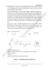
not restrained in a rotary sense (i.e. preferably by the rear axle) as shown in Figure
12. Fit a suitable roller to the front axle in order to permit the frame to flex in a
fore/aft sense under the test forces.
Insert intended seat post at minimum insertion depth or equivalent to a seat-stem to
a depth of 75 mm in the top of the seat-tube and secure this to the manufacturer's
instructions by the normal clamp. Securely attach a horizontal, rearward extension (E
in Figure 12) to the top of this bar such that its length (dimension h3 in Figure 12)
places Point H in a position equivalent to that of the centre of the saddle-clamp with
the bicycle at its maximum saddle height recommended for the particular frame, or
if the maximum saddle height information is not available dimension h3 shall be 250
mm.
Apply cycles of dynamic, vertically-downward forces of F 5 at a point 70 mm behind
the intersection of the axes of the solid steel bar and the extension piece, E, as
shown in Figure 12 for 50 000 test cycles. The forces are given in Table 8. The
maximum test frequency shall be maintained as specified in 4.3.1.5.
Table 8 — Forces on seat-stem
Force in N
Forces,F 5 1200
E Horizontal, rearward extension
H Position equivalent to that of the centre of the saddle-clamp with the bicycle
1 Free-running roller
2 Steel bar
3 Rigid, pivoted mounting for rear axle attachment point
Figure 12 — Frame: fatigue test with a vertical force
Page 33 for 43