Page 27 - 20190101 part 6 (EN)
P. 27
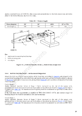
Apply a rearward force of 1 000 N to the torque arm perpendicular to the fork steerer axis and in the
plane of the wheel. Maintain this force for 1 min.
Table 10 — Fixture length
Wheel diameter 24ʺ 26ʺ 650b 29ʺ or 700c
Arm length, L 2 305 330 349 368
Key
1 rigid mount incorporating head bearings
2 brake mounting point
3 test adaptor
Figure 11 — Fork for hub/disc brake — Static brake-torque test
5.6.3 Fork for hub/disc brake — Brake mount fatigue test
Mount the fork in a fixture representative of the head tube according to Annex B and gripped in the
normal head-bearings, fit an axle to the fork, and mount on the axle a pivoted, straight adaptor as shown
in Figure 12 to provide a torque arm of L 2 in length (see Ta ble 10) and a suitable attachment for the brake
mounting point.
5.6.3.1 Stage 1
Apply repeated, dynamic forces of Stage 1 Force rearward to the end of the torque arm,
perpendicular to the fork steerer axis and in the plane of the wheel (as shown in Figure 12) for Stage 1
C 2 cycles (see Table 11). The maximum test frequency shall be maintained as specified in TBIS 4210-
3:2016, 4.5.
If the fork meets the requirement as specified in TBIS 4210-2:2017, 4.9.7.2, and conduct stage 2 of
bending fatigue test with the assembly in the same mountings.
5.6.3.2 Stage 2
Apply repeated, dynamic forces of Stage 2 Force rearward to the end of the torque arm,
perpendicular to the fork steerer axis and in the plane of the wheel (as shown in Figure 12) for Stage 2
C 2 cycles (see Table 11). The maximum test frequency shall be maintained as specified in TBIS 4210-
3:2016, 4.5.
19