Page 12 - 2016-v.1-Part 8(EN)
P. 12
TBIS 4210-8:2016
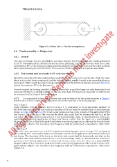
Figure 5 — Drive belt — Tensile strength test
4.6 Crank assembly — Fatigue test
4.6.1 General
Two types of fatigue test are specified for mountain bicycles: the first test with the cranks positioned
at 45° to the horizontal to simulate the forces due to pedalling, and the second test with the cranks
positioned at 30° to the horizontal, which has been found to simulate the forces due the rider standing
on the pedals during the descent of hills. The two tests shall be conducted on separate assemblies.
4.6.2 Test method with the cranks at 45° to the horizontal
Mount the assembly of the two pedal-spindle adaptors, the drive side and non-drive side crank, the chain
wheel set (or other drive component), and the bottom-bracket spindle located on its normal-production
bearings in a fixture with bearing housings representative of the bottom-bracket (as shown in Figure 6).
Incline the cranks at 45° to the horizontal.
Prevent rotation by locating a suitable length of drive chain around the largest or only chain wheel and
securing it firmly to a suitable support, or, for any other type of transmission (e.g. belt- or shaft-drive)
by securing the first stage of the transmission.
NOTE It is permissible to have the non-drive side crank in either of the two positions shown in Figure 6,
provided the test force is applied in the appropriate direction as specified in the next paragraph.
4.6.2.1 Stage 1
Apply repeated, vertical, dynamic forces of stage 1 F 2 alternately to the pedal-spindle adaptors of
the drive side and non-drive side crank at a distance of 65 mm from the outboard face of each crank (as
shown in Ta ble 2 and Figure 6) for C test cycles (where one test cycle consists of the application of the
two forces). The direction of the force on the drive side crank shall be downwards and that on the
non-drive side crank shall be upwards for a rearward-pointing crank, or downwards for a forward-
pointing crank. During application of these test forces, ensure that the force on a pedal-spindle
adaptor falls to 5 % or less of the peak force before commencing application of the test force to the other
pedal-spindle adaptor. The maximum test frequency shall be maintained as specified in TBIS 4210-
3:2016, 4.5.
4.6.2.1 Stage 2
With the same mounted as in 4.6.2.1, repeated, vertical, dynamic forces of stage 2 F2 as shown in
Tab. 2 and Fig. 6 for C test cycles, where one test cycle consists of the application and removal of the two
test forces. The direction of the force on the drive side crank shall be downwards and that on the
non-drive side crank shall be upwards for a rearward-pointing crank, or downwards for a forward-
pointing crank. During application of these test forces, ensure that the force on a pedal-spindle
adaptor falls to 5 % or less of the peak force before commencing application of the test force to the other
pedal-spindle adaptor. The maximum test frequency shall be maintained as specified in TBIS 4210-
3:2016, 4.5.
6