Page 10 - 2016-v.1-Part 8(EN)
P. 10
TBIS 4210-8:2016
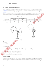
4.3 Pedal — Dynamic durability test
Screw each pedal securely into a threaded hole in a rotable test shaft at 30 to the horizontal as shown
o
in Figure 4 and suspend a mass of M at the centre of the pedal width by means of a tension spring to
each pedal, the object of the springs being to minimize oscillations of the load. The masses are given in
Ta ble 1.
Drive the shaft at a speed not exceeding 100 min −1 for a total of 100 000 revolutions. If the pedals are
provided with two tread surfaces, they shall be turned through 180° after 50 000 revolutions.
Table 1 — Masses on pedal
City and trekking Young adult bicy-
Bicycle type bicycles cles Mountain bicycles Racing bicycles
Mass, M 80 80 90 90
kg
Key
1 pedal
2 test shaft
3 mass
4 tension spring
Figure 4 — Pedal/pedal-spindle — Dynamic durability test
4.4 Drive system — Static strength test
4.4.1 Test method for drive system with chain
4.4.1.1 General
Conduct the drive system static load test on an assembly comprising the frame, pedals, transmission
system, rear wheel assembly, and, if appropriate, the gear-change mechanism. Support the frame with
the central plane vertical and with the rear wheel held at the rim to prevent the wheel from rotating.
4