Page 97 - TBIS_15194-2019_(EN)_3nd
P. 97
TBIS 15194:2019
4.3.12.5.2.1 Test method (1)
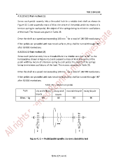
Screw each pedal securely into a threaded hole in a rotable test-shaft as shown in
Figure 41-1 and suspend a mass of M at the centre of the pedal width by means of a
tension-spring to each pedal, the object of the springs being to minimize oscillations
of the load. The masses are given in Table 28.
−1
Drive the shaft at a speed not exceeding 100 min for a total of 100 000 revolutions.
If the pedals are provided with two tread surfaces, they shall be turned through 180°
after 50 000 revolutions.
4.3.12.5.2.2 Test method (2)
o
Screw each pedal securely into a threaded hole in a rotable test shaft at 30 to the
horizontal as shown in Figure 41-2 and suspend a mass of M at the centre of the
pedal width by means of a tension spring to each pedal, the object of the springs
being to minimize oscillations of the load. The masses are given in Table 28.
−1
Drive the shaft at a speed not exceeding 100 min for a total of 100 000 revolutions.
If the pedals are provided with two tread surfaces, they shall be turned through 180°
after 50 000 revolutions.
Table 28 — Masses on pedal
Type city and trekking young adult mountain-bicycle racing-bicycle
bicycle bicycle
Mass,kg 80 80 90 90
踏板 踏板
旋轉軸
W W
Figure 41-1 — Pedal/pedal-spindle: dynamic durability test
第 89 頁共 162 頁