Page 102 - TBIS_15194-2019_(EN)_3nd
P. 102
TBIS 15194:2019
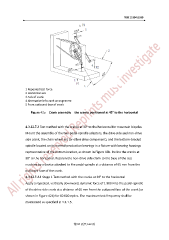
1 Repeated test force
2 Horizontal axis
3 Axis of crank
4 Alternative left crank arrangement
5 From outboard face of crank
Figure 42a-Crank assembly-the cranks positioned at 45° to the horizontal
4.3.12.7.3 Test method with the cranks at 30° to the horizontal for mountain bicycles
Mount the assembly of the two pedal-spindle adaptors, the drive side and non-drive
side crank, the chain wheel set (or other drive component), and the bottom-bracket
spindle located on its normal-production bearings in a fixture with bearing housings
representative of the bottom-bracket, as shown in Figure 42b. Incline the cranks at
30° to the horizontal. Restrain the non-drive side crank to the base of the test
machine by a device attached to the pedal-spindle at a distance of 65 mm from the
outboard face of the crank.
4.3.12.7.3.1 Stage 1 Test method with the cranks at 30° to the horizontal
Apply a repeated, vertically downward, dynamic force of 1 800 N to the pedal-spindle
of the drive side crank at a distance of 65 mm from the outboard face of the crank (as
shown in Figure 42b) for 60 000 cycles. The maximum test frequency shall be
maintained as specified in 4.3.1.5.
第 94 頁共 162 頁