Page 51 - TBIS_15194-2019_(EN)_3nd
P. 51
TBIS 15194:2019
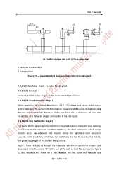
b) Combined stem and quill c) Stem extension
1 Minimum insertion depth
2 Clamping block
Figure 12 — Handlebar and stem assembly: lateral bending test
4.3.6.6.2 Handlebar -stem – Forward bending test
4.3.6.6.2.1 General
Conduct the test in two stages on the same assembly as follows.
4.3.6.6.2.2 Requirement for Stage 1
When tested by the method described in 4.3.6.6.2.3, there shall be no visible cracks
or fractures and the permanent deformation measured at the point of application of
the test force and in the direction of the test force shall not exceed 10 mm. And
record the ratio between weight and rigidity in the test result.
4.3.6.6.2.3 Test method for Stage 1
For stems which have a quill for insertion in to a fork steerer, clamp the quill securely
in a fixture to the minimum insertion depth or, for stem extensions which clamp
directly on to an extended fork steerer, clamp the handlebar-stem extension
securely on to a suitable, solid-steel bar and clamp the bar in securely in a fixture,
the projecting length of the bar not being critical.
Apply a force F3(Table 4) through the handlebar attachment point in a forward and
downward direction and at 45° to the axis of the quill or steel bar as shown in Figure
13 and maintain this force for 1 min. Release the test force and measure any
第 43 頁共 162 頁