Page 50 - TBIS_15194-2019_(EN)_3nd
P. 50
TBIS 15194:2019
4.3.6.6 Steering assembly – Static strength and security tests
4.3.6.6.1 Handlebar and stem assembly – Lateral bending test
4.3.6.6.1.1General
This test is for manufacturers who produce handlebars and stems or for cycle
manufacturers.
4.3.6.6.1.2 Requirement
When tested by the method described in 4.3.6.6.1.3, there shall be no cracking or
fracture of the handlebar, stem or clamp-bolt and the permanent deformation
measured at the point of application of the test force shall not exceed 15 mm. And
record the ratio between weight and rigidity in the test result.
4.3.6.6.1.3 Test method
Assemble the handlebar and stem in accordance with the manufacturer's
instructions and, unless the handlebar and stem are permanently connected, e.g. by
welding or brazing, align the grips portion of the handlebar in a plane perpendicular
to the stem axis (see Figure 12). For stems which have a quill for insertion in to a fork
steerer, clamp the quill securely in a fixture to the minimum insertion depth, or, for
stem extensions which clamp directly on to an extended fork steerer attach the
extension to a fork steerer according to the manufacturer's instructions and clamp
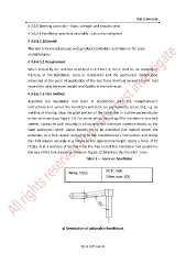
this fork steerer securely in a fixture to the appropriate height. Apply a force of F2
(Table 3) at a distance of 50 mm from the free end of the handlebar and parallel to
the axis of the fork steerer as shown in Figure 12. Maintain this force for 1 min.
Table 3 — Force on handlebar
Force, F2(N) MTB: 1000
Other type: 800
800 N
a) Orientation of adjustable handlebars
第 42 頁共 162 頁