Page 12 - 20190101 part 7 (EN)
P. 12
TBIS 4210-7:2019
Table 1 — Forces on rim
Forces in newtons
City and trek- Young adult Mountain Racing bicy-
Bicycle type king bicycles bicycles bicycles cles
Force 250 250 370 250
F
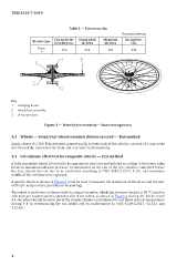
Key
1 clamping fixture
2 wheel/tyre assembly
3 drive sprockets
Figure 3 — Wheel/tyre assembly— Static strength test
4.3 Wheels — Front/rear wheel retention devices secured — Test method
Apply a force of 2 300 N distributed symmetrically to both ends of the axle for a period of 1 min in the
direction of the removal of the front and rear wheel independently.
4.4 Greenhouse effect test for composite wheels — Test method
A fully assembled wheel, fitted with the appropriate size tyre and inflated according to the lower value
between maximum inflation pressure recommended on the rim or the tyre, shall be controlled before
the test; lateral run-out has to be controlled according to TBIS 4210-2:2017, 4.10.1 and maximum
widths of the rim have to be reported.
A specific bench as shown in Figure 5 could be used to measure the maximum width all around the rim
with tyre and pressure (continuous measuring).
The wheel is laid down on the ground of a climate chamber, which has been pre-heated at 80 °C, leant on
axle and tyre support points, sprocket side of the wheel, as shown in Figure 4, during 4 h. At the end of
4 h, the wheel should be taken out of the climate chamber and allowed to cool down at room temperature
during 4 h to re-measuring the rim width and its conformance to TBIS 4210-2:2017, 4.11.6.1 and
4.11.6.2.
4