Page 11 - 20190101 part 7 (EN)
P. 11
TBIS 4210-7:2019
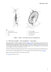
Key
1 instrument stand 5 hub axle support
2 dial-gauge (concentricity) 6 dial-gauge (lateral run-out)
3 rim 7 instrument stand
4 spoke 8 roller indicator
Figure 2 — Wheel — Rotational accuracy for racing bicycles
4.2 Wheel/tyre assembly — Static strength test — Test method
Clamp and support the wheel suitably as shown in Figure 3. Apply a pre-load of 5 N on the rim at one
spoke perpendicular to the plane of the wheel as shown in Figure 3. Record the zero position of the rim
at the point of load application as shown. Then apply a static force of F given in Ta ble 1 for a duration of
1 min. Reduce the load to 5 N and allow a 1 min settling time. After this settling time and with the 5 N
load still applied, re-measure the position of the rim.
The wheel shall be fitted with the appropriate size tyre and inflated to the maximum inflation pressure.
In the case of a rear wheel, apply the force from the sprocket side of the wheel as shown in Figure 3.
Repeat the above measurement once between two spokes.
See Annex A for fatigue testing.
3