Page 15 - 2016-v.1-Part 5(EN)
P. 15
TBIS 4210-5:2016
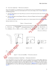
4.7 Bar end to handlebar — Torsional security test
Secure the handlebar in a suitable fixture and assemble the bar end on the handlebar tightening the
fixings in accordance with the bar end manufacturer’s instructions. Apply a force of F 5 (see Ta ble 6) to
the following position:
a) if the bar end’s length is more than 100 mm, at a distance of 50 mm from the free end of the bar end
[see Figure 8 a)];
b) if the bar end’s length is from 50 mm to 100 mm, at a distance of 50 mm from the axis of the handlebar
[see Figure 8 b)];
c) if the bar end’s length is less than 50 mm, apply a load to the mid-point of the bar end [see Figure 8 c)].
Maintain this force for 1 min.
Table 6 — Forces on bar end
Forces in newtons
City and trekking
Bicycle type Young adult bicycles Mountain bicycles Racing bicycles
bicycles
Force, F 5 300 300 500 300
Dimensions in millimetres
a) L > 100 b) 100 ≥ L ≥ 50 c) 50 > L
Key
L bar end’s length
Figure 8 — Bar end to handlebar — Torsional security test
4.8 Aerodynamic extensions to handlebar — Torsional security test
Secure the handlebar in the stem intended for use and assemble the extension on the handlebar tightening
all the fixings in accordance with the extension, handlebar, and handlebar stem manufacturer’s
instructions. The steering axis should be vertical. Apply a vertical force of 300 N to the extension on the
position giving the maximum torque to the clamps as shown in Figures 9 a) and b). The exact method
of applying the force can vary with the type of aerodynamic extension, and an example is shown in
Figure 9.
9