Page 13 - 2016-v.1-Part 5(EN)
P. 13
TBIS 4210-5:2016
4.4.2 Test method for stage 2
With the handlebar stem mounted as in stage 1 (see 4.4.1), apply a progressively increasing force in
the same position and direction as in 4.4.1 until either the force reaches a maximum of F 4 or until the
handlebar stem deflects 50 mm measured at the point of application of the test force and in the direction
of the test force. If the stem does not yield or continue to yield, maintain the force for 1 min. The forces
are given in Ta ble 3.
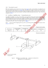
4.5 Handlebar to handlebar stem — Torsional security test
Assemble the handlebar correctly in the handlebar stem with the locking system tightened in accordance
with the manufacturer’s instructions and clamp the handlebar stem securely in a fixture to the minimum
insertion depth and with its axis vertical. Apply a torque of T 1 about the centreline of the stem-clamp.
Divide the torque equally by vertically, downward forces applied to both sides of the handlebar and
maintain the forces for 1 min. The torque is given in Ta ble 4.
NOTE The exact method of applying the torque will vary with the type of handlebar, and an example is shown
in Figure 6 (T 1 = F × L).
Table 4 — Torque on handlebar
Torques in newton metres
City and trekking Young adult bicy-
Bicycle type bicycles cles Mountain bicycles Racing bicycles
Torque, T 1 60 60 80 60
Dimensions in millimetres
Key
1 minimum insertion depth
2 clamping block
Figure 6 — Handlebar to handlebar stem — Torsional security test for
applying forces to clamping block
7