Page 16 - TBIS_79010-2019_(EN)_1nd
P. 16
TBIS 79010:2019
4.2.2.3 Attachment of brake assembly and cable requirements
Cable pinch-bolts shall not sever any of the cable strands when assembled to the
manufacturer's instructions. In the event of a cable failing, no part of the brake
mechanism shall inadvertently inhibit the rotation of the wheel.
The cable end shall either be protected with a cap that shall withstand a removal
force of not less than 20 N or be otherwise treated to prevent unravelling.
NOTE See 4.1.3 in relation to fasteners.
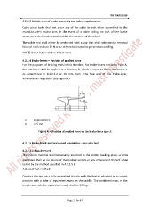
4.2.2.4 Brake-levers – Position of applied force
For the purposes of braking tests in this standard, for brake-levers similar to Type A,
the test force shall be applied at a distance, b, which is equal to either dimension a
as determined in 4.2.2.2.2 or 25 mm from the free end of the brake-lever,
whichever is the greater (see Figure 4).
F Applied force
b =25 mm
Figure 4 —Position of applied force on the brake-lever type A
4.2.2.5 Brake-block and brake-pad assemblies – Security test
4.2.2.5.1 Requirement
The friction material shall be securely attached to the holder, backing-plate, or shoe
and there shall be no failure of the braking system or any component thereof when
tested by the method specified in 4.2.2.5.2.
4.2.2.5.2 Test method
Conduct the test on a fully-assembled bicycle with the brakes adjusted to a correct
position with a rider or equivalent mass on the saddle. The combined mass of the
bicycle and rider (or equivalent mass) shall be 100 kg.
Page 12 for 43