Page 65 - TBIS_15194-2019_(EN)_3nd
P. 65
TBIS 15194:2019
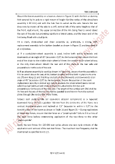
Mount the frame assembly on a base as shown in Figure 21 with the fork or dummy
fork secured by its axle to a rigid mount of height Rw (the radius of the wheel/tyre
assembly ± 30 mm) and with the hub free to swivel on the axle. Secure the rear
drop-outs by means of the axle to a stiff, vertical link of the same height as that of
the front, rigid mount, the upper connection of the link being free to swivel about
the axis of the axle but providing rigidity in a lateral plane, and the lower end of the
link being fitted with a ball-joint.
Fit a crank, chain-wheel and chain assembly or, preferably, a strong, stiff,
replacement assembly to the bottom bracket as shown in Figure 21 and described in
a) or b) below.
a) If a crank/chain-wheel assembly is used, incline both cranks forwards and
downwards at an angle of 45° (accurate ± 2,0°) to the horizontal and secure the front
end of the chain to the middle chain-wheel of three, the smaller chain-wheel of two,
or the only chain-wheel. Attach the rear end of the chain to the rear axle and
perpendicular to the axis of the axle.
b) If an adaptor assembly is used (as shown in Figure 21), ensure that the assembly is
free to swivel about the axis of the bottom-bracket and that both replacement arms
are 175 mm long (L) and that they are both inclined forwards and downwards at an
angle of 45° (accurate ± 2,0°) to the horizontal. Secure the position of the crank
replacement arms by a vertical arm (which replaces the chain-wheel) and a tie-rod
which has ball-joints at both ends and which is attached to the rear axle
perpendicular to the axis of the rear axle. The length of the vertical arm (Rc) shall be
75 mm and the axis of the tie-rod shall be parallel to and 50 mm from the vertical
plane through the centre-line of the frame.
Subject each pedal-spindle (or equivalent adaptor component) to a repeated
downward force of F1at a position 150 mm from the centre-line of the frame in a
vertical, transverse plane and inclined at 7,5° (accurate to within ± 0,5°) to the
fore/aft plane of the frame as shown in Table 14 and Figure 21 —During application
of these test forces, ensure that the force on a “pedal-spindle” falls to 5 % or less of
the peak force before commencing application of the test force to the other
“pedal-spindle”.
Apply the test forces for 120 000 test cycles where one test cycle consists of the
application and removal of the two test forces. The maximum test frequency shall be
maintained as specified in 4.3.1.5.
第 57 頁共 162 頁