Page 8 - 2016-v.1-Part 9(EN)
P. 8
TBIS 4210-9:2016
Table 1 — Forces on saddle
Forces in newtons
City and trekking
Bicycle type bicycles Young adult bicycles Mountain bicycles Racing bicycles
Vertical force, F 1 1000
Horizontal force, F 2 450
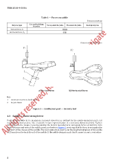
Dimensions in millimetres
a) Vertical force b) Horizontal force
Key
1 minimum insertion-depth mark
2 bicycle frame
Figure 1 — Saddle/seat-post — Security test
4.3 Saddle — Static strength test
Position the saddle in its maximum rearward direction as defined by the saddle manufacturer’s rail
markings or instructions, into a suitable fixture representative of a seat-post clamp assembly. Tighten
the clamps to the torque recommended by the bicycle manufacturer, and apply forces of 440 N in turn
under the rear and nose of the saddle cover, as shown in Figure 2, ensuring that the force is not applied to
any part of the chassis of the saddle. The load application point is on the longitudinal plane of the saddle
at 25 mm from the back (front) of the saddle. If the saddle design is such that it cannot accept a centreline
2