Page 37 - 20190101 part 6 (EN)
P. 37
TBIS 4210-6:2019
Annex E
(informative)
Stiffness measurement of frame
E1: General
1. The test method of the item is applicable to the frames defined by TBIS 4210.
2. It is necessary to use a new frame/front fork set, and completely assembling process by the
default head set. If only the frame is provided, it is allowed to replace the original front fork
by the simulated front fork with the same length (as described in Annex A of TBIS 4210-
6:2017); however, it stiffness should not be lower than the original front fork.
3. If the sample to be executed is a shock frame, it is necessary to use the stiffness connection
bar to replace the shock component; please note that the gap between the fixation points of
two ends of the connection bar and the strength of the lateral stiffness in order to simulate
the original configuration of the frame.
4. The force should be slowly increased to reach the setting in order to avoid that the shock
influences the deformation of the frame.
5. Before the force is applied, it is necessary to use 20% of the setting value of the force as the
preload, and keep applying the force for 1 minute; after the preload is executed for several
times, please release the preload, and reset the displacement; then, please use 100% of the
force to execute the test.
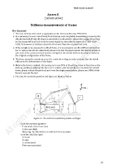
6. The code for constrain position and types are show as below:
R
F
Ball joint
Figure E1 The code for constrain position and type.
Code for constrain position:
F: the shaft of the front fork,
R: the rear shaft,
Ball joing: the link with rear shaft and the base plane
Code for constrain type:
U: move
R: spin
0: constrained
Free: unconstrained
29