Page 19 - 2018-v.3-Part 2(EN)
P. 19
b) It shall incorporate a permanent stop to prevent it from being drawn out of the fork steerer such as
to leave the insertion less than the amount specified in item a).
4.7.4 Handlebar stem to fork steerer — Clamping requirements
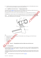
The distance g (see Figure 4) between the top of the handlebar stem and the top of the fork steerer to
which the handlebar stem is clamped shall not be greater than 5 mm.
The upper part of the fork steerer to which the handlebar stem is clamped shall not be threaded.
The dimension g, shall also ensure that the proper adjustment of the steering system can be achieved.
NOTE For aluminium and composite fork steerer, the avoidance of any internal device that could damage the
internal surface of the fork steerer is recommended.
Key
g distance between the upper, clamping part of the handlebar stem and the upper part of the fork steerer
1 handlebar stem
2 extended fork steerer
3 spacer rings
4 head set
5 head tube
Figure 4 — Clamping between the handlebar stem and fork steerer
4.7.5 Steering stability
The steering shall be free to turn through at least an angle of θ 1 either side of the straight-ahead position
and shall exhibit no tight spots, stiffness, or slackness in the bearings when correctly adjusted. The
values are given in Ta ble 4.
A minimum of 25 % of the total mass of the bicycle and rider shall act on the front wheel when the rider
is holding the handlebar grips and sitting on the saddle, with the saddle and rider in their most rearward
positions.
NOTE Recommendations for steering geometry are given in Annex A.
© ISO 2014 – All rights reserved 11